Cap Start Motor Wiring Diagram. Web split phase permanently connected capacitor electric motor wiring diagram. The first circuit is the starting circuit, which is responsible for providing.
⚡ Single Phase Capacitor Start Capacitor Run Motor Wiring Diagram ⭐ from bestpricescraftsmantablelamps.blogspot.com
However yellow is the start switch blue is. The first circuit is the starting circuit, which is responsible for providing. Web all the information is there.
However Yellow Is The Start Switch Blue Is.
If the cover from the compressor relay/start device is removed, you should find three pins for the unit, labeled r, c, and s. Web a start capacitor holds a charge that it uses to help the motor at start up, providing additional torque so that motor can turn the load from a stand still. The wiring colours to the motor suggest that this is a three phase motor, just to confuse me.
Web Wiring Diagrams Show How The Wires Are Linked, Where They Should Be Located In The Device And The Physical Connections Between All The Components.
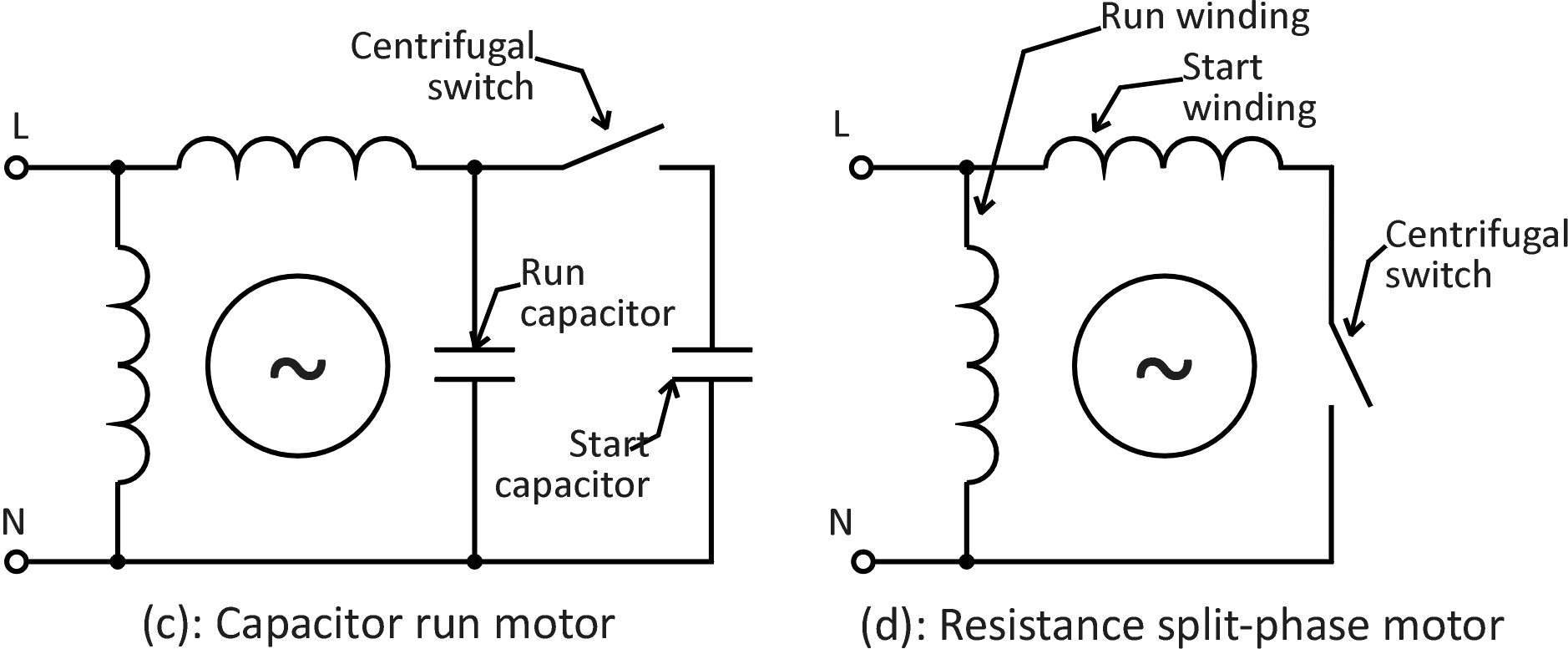
Web the basic wiring diagram for a capacitor start run motor consists of two separate circuits. The first circuit is the starting circuit, which is responsible for providing. Web all the information is there.
Web With A Thorough Understanding Of The Wiring Diagrams, The System Can Be Optimized For Maximum Performance, Thus Helping To Reduce Energy Costs And Improve.
Web split phase permanently connected capacitor electric motor wiring diagram. Typical wiring diagram line diagrams show circuits of the operation of the controller. Web 3 in 1 start capacitor wiring diagram.